Corrosion Types
Finding a proper materials solution means starting at the source of the problem.
> View and download a print-friendly version of the Materials Selection Guide
General (Uniform) Corrosion
General, or uniform corrosion, is the easiest to identify. Learn to spot it.
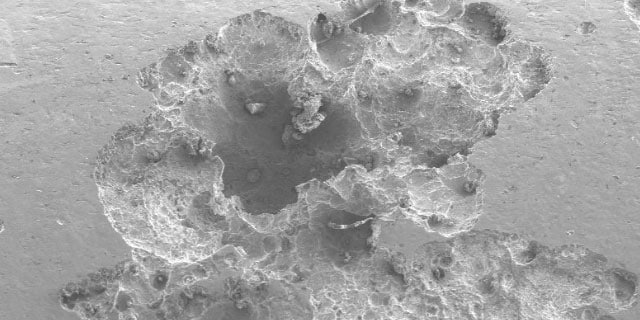
Localized Pitting Corrosion in Chloride-Containing Media
Learn how pitting forms on material surfaces.
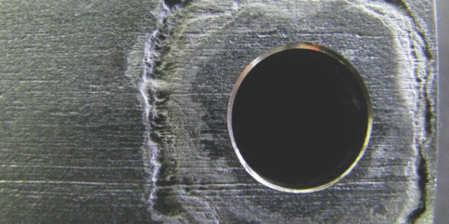
Localized Crevice Corrosion in Chloride-Containing Media
See how corrosion can form in a fluid system's crevices and tight spaces.
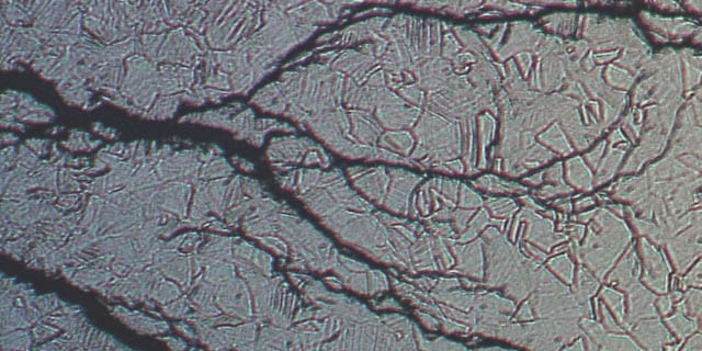
Stress Corrosion Cracking in Chloride-Containing Media
Learn more about how stress corrosion cracking can result in material failure.
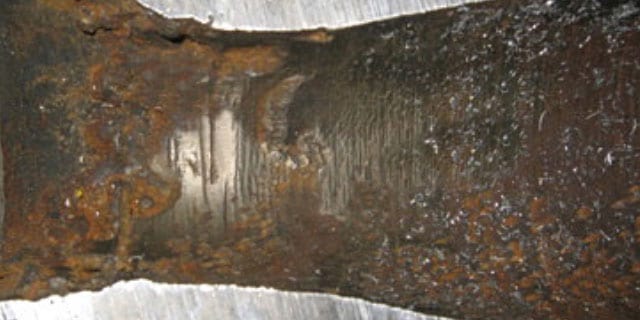
Sour Gas Cracking or Sulfide Stress Cracking at High Hydrogen Sulfide (H2S) Partial Pressure
Sour gas environments can lead to sulfide stress corrosion. Discover how it forms.
Hydrogen Embrittlement
Hydrogen atoms can diffuse into metals, making them brittle. Selecting resistant materials can help.
Galvanic Corrosion in the Presence of an Electrolyte
To avoid galvanic corrosion, know what causes it.
General (Uniform) Corrosion
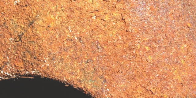
The most well-known type of corrosion is also the easiest to spot and predict. It is unusual — but not unheard of — for general corrosion to lead to disastrous failures. For this reason, general corrosion is often regarded as an eyesore rather than a serious problem. General corrosion occurs relatively uniformly across a metal surface. The gradual decrease of the wall thickness of a component must be considered when calculating pressure ratings.
How It Forms
In a marine or other corrosive environment, the surface of carbon or low-alloy steel begins to break down, allowing for the formation of an iron oxide scale which grows thicker in time until it spalls off and new scale forms.
Can Be Measured By
- How fast the material recedes on an annual basis. For example, unprotected carbon steel may recede in a marine environment by 1 mm every year.
- The weight loss that is experienced by an alloy when in contact with corrosive fluids, typically measured in milligrams per square centimeter of exposed material per day
Potential Solutions
316/316L Stainless Steel; 6-Moly Alloys; Alloy 2507; Alloy 825; Alloy 625; Alloy C-276; Alloy 400
Localized Pitting Corrosion in Chloride-Containing Media
Pitting corrosion causes small cavities, or pits, to form on the surface of a material. Although detectable by thorough visual inspection, these pits can grow deep enough to perforate tubing. Pitting is more often observed in high-chloride environments at elevated temperatures.
How It Forms
When the protective layer of oxide (or passive oxide layer) on the surface of the metal breaks down, the metal becomes susceptible to loss of electrons. This causes iron in the metal to dissolve into a solution in the more anodic bottom of the pit, diffuse toward the top, and oxidize to iron oxide, or rust. The iron chloride solution concentration in a pit can increase and become more acidic as the pit gets deeper. These changes result in accelerated growth of the pit, perforation of tubing walls, and leaks.
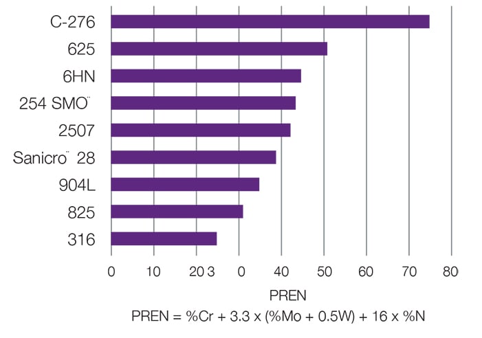
Pitting corrosion is best prevented by proper alloy selection. Different metals and alloys can be compared using their Pitting Resistance Equivalence Number (PREN), which is calculated from the chemical composition of the material. PREN increases with higher levels of chromium, molybdenum, and nitrogen.
Potential Solutions
6-Moly Alloys; Alloy 2507; Alloy 825; Alloy 625; Alloy C-276; Alloy 400
Localized Crevice Corrosion in Chloride-Containing Media
In a typical fluid system, crevices exist between tubing and tube supports or tube clamps, between adjacent tubing runs, and underneath dirt and deposits that may have accumulated on surfaces. Crevices are virtually impossible to avoid in tubing installations, and tight crevices pose the greatest danger for corrosion to occur.
How It Forms
Like pitting corrosion, crevice corrosion starts with the breakdown of the passive oxide layer that protects the metal. This breakdown leads to the formation of small pits. The pits grow larger and deeper until they cover the whole crevice.
In some places, tubing can be perforated. Crevice corrosion occurs at far lower temperatures than pitting corrosion.
Potential Solutions
6-Moly Alloys; Alloy 2507; Alloy 825; Alloy 625; Alloy C-276; Alloy 400
Material Matters
When seawater diffuses into a crevice, some Fe++ ions dissolve and cannot rapidly diffuse out of a tight crevice. In salt water, negatively charged chloride ions (Cl-) are attracted by these positively charged Fe++ ions and begin to diffuse into the crevice. As the chloride concentration increases, the crevice solution becomes more corrosive, causing more iron to dissolve, which in turn attracts more chloride ions to diffuse into the crevice. Ultimately, the crevice solution turns into an acidic solution with high chloride concentration, which is very corrosive.
Stress Corrosion Cracking in Chloride-Containing Media
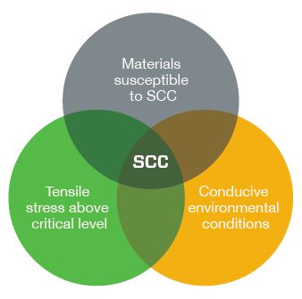
Stress corrosion cracking (SCC) is dangerous because it can destroy a component at stress levels below the yield strength of an alloy. In the presence of chloride ions, austenitic stainless steels are susceptible to SCC. The ions interact with the material at the tip of a crack where tensile stresses are highest, making it easier for the crack to grow. While in progress, SCC can be difficult to detect, and final failure can occur suddenly.
How It Forms
For SCC to occur, three conditions must be met simultaneously:
- The metal must be susceptible to SCC
- Environmental (fluid or temperature) conditions conducive to SCC must exist
- The tensile stress (applied + residual) must be above critical level
Potential Solutions
6-Moly Alloys; Alloy 2507; Alloy 825; Alloy 625; Alloy C-276; Alloy 400
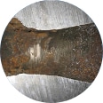
Sour Gas Cracking or Sulfide Stress Cracking at High Hydrogen Sulfide (H2S) Partial Pressure
Sour gas cracking, also known as sulfide stress cracking (SSC), is the deterioration of metal due to contact with hydrogen sulfide (H2S) and moisture. H2S becomes severely corrosive in the presence of water. This condition can lead to embrittlement of the material, resulting in cracking under the combined action of tensile stress and corrosion.
How It Forms
The risk of SSC increases when the following factors increase:
- The metal must be susceptible to SSC
- The environment must be sufficiently sour (high in H2S)
- The tensile stress (applied + residual) must be above a critical level
Increased risk for SSC occurs when greater amounts of the following occur, compared to materials less likely to experience SSC:
- Material hardness/tensile strength
- Hydrogen ion concentration (lower pH value)
- H2S partial pressure
- Total tensile stress (applied + residual)
- Exposure time
The risk of SSC increases at lower temperatures where materials tend to be less ductile.
Potential Solutions
Material Matters
The NACE MR0175/ISO 15156 standard describes suitable materials for sour environments in oil and gas production. For more help selecting components for sour oilfields, refer to Selecting fluid system components for use in sour oilfields.

Hydrogen Embrittlement
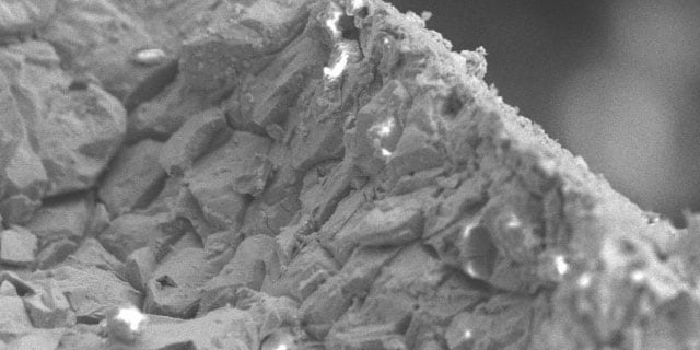
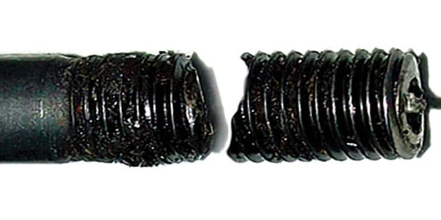
Hydrogen atoms can diffuse into metals, making them brittle. All materials susceptible to hydrogen embrittlement are also very susceptible to stress corrosion cracking.
How It Forms
Hydrogen-induced cracking can occur if the metal is subject to static or cyclic tensile stress. Hydrogen can cause changes in the mechanical properties and behavior of the metal, including:
- Reduction of ductility (elongation and reduction of area)
- Reduction of impact strength and fracture toughness
- Increased fatigue behavior
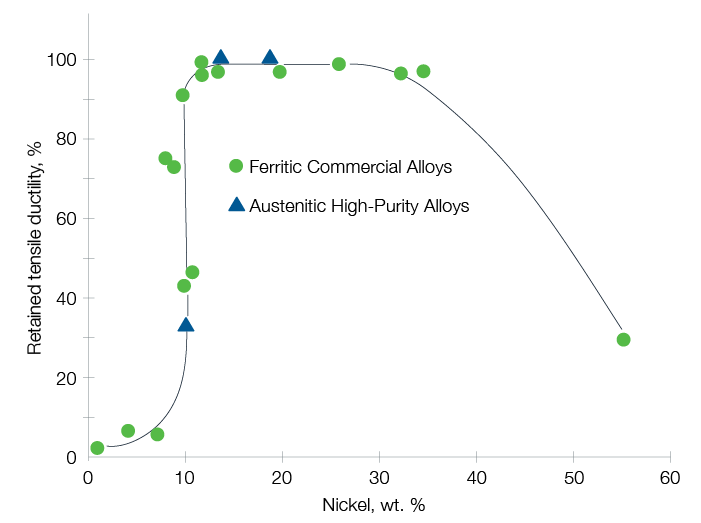
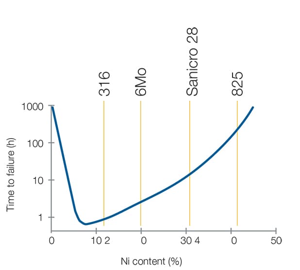
Hydrogen embrittlement can be avoided by selecting material resistant to hydrogen, such as austenitic alloys with nickel content between 10% and 30%.
Source: G.R. Caskey, Hydrogen Compatibility Handbook for Stainless Steels (1983)
Potential Solutions
Intergranular Corrosion
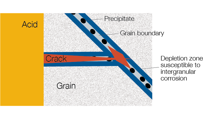
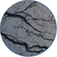
To understand intergranular corrosion (IGC), consider that all metals consist of individual grains. Within each grain, the atoms are systematically arranged, forming a three-dimensional lattice. IGC attacks the material along the grain boundaries (where the grains that make up the metal come together).
How It Forms
During welding, heat treatment, or exposure to high temperatures, carbides can begin to form on grain boundaries. These carbide precipitates can grow larger in time. This carbide formation affects the uniform distribution of elements within the metal by robbing material adjacent to grain boundaries of important elements, such as chromium. When corrosive fluids (like acids) attack the chromium-depleted regions, intergranular cracks can form. These cracks can propagate throughout a material and stay undetected, making IGC a dangerous form of corrosion.
Potential Solutions
Galvanic Corrosion in the Presence of an Electrolyte
Galvanic corrosion occurs when materials with a dissimilar electrode potential are in contact in the presence of an electrolyte.
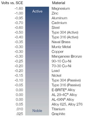
The passive layer on stainless steel consists of a very thin chromium-rich oxide film that automatically forms in ambient air and protects the material from corrosion. The passive layer makes a material more noble and less susceptible to corrosion. The compatibility of metals can be determined by the Anodic Index, which describes the potential or voltage difference of metals measured in seawater against a standard electrode.
How It Forms
When the potential difference between two dissimilar metals in the presence of an electrolyte is too great, the material’s passive layer begins to break down.
Potential Solutions
To avoid galvanic corrosion, choose materials with a voltage difference that does not exceed 0.2V. For example, a 316 stainless steel fitting (-0.05V) with 6-Moly tubing (0.00V) would result in a voltage of 0.05V between the two alloys. This voltage is significantly less than 0.2V, meaning the risk of galvanic corrosion is low.
For more information, check out these additional helpful reference materials from Swagelok.
> View and download a print-friendly version of the Materials Selection Guide
1 Reprinted from Science Direct, Volume 1, Issue 3, S.M.R. Ziaei, A.H. Kokabi, M. Nasr-Esehani, Sulfide Stress Corrosion Cracking and Hydrogen Induced Cracking of A216-WCC Wellhead Flow Control Valve Body case study, Pages 223-224, July 2013 with permission from Elsevier.
2 Hydrogen Embrittlement Image Courtesy of Salim Brahimi, IBECA Technologies Corp.

